Welcome to Changsha Mining Equipment Co., Ltd.
Advanced IGBT Chopper Control in 5-Ton Battery Locomotives: A Detailed Technical Guide
In the demanding world of underground mining and tunneling, the reliability and efficiency of transport equipment are non-negotiable. The 5-ton battery locomotive is a workhorse in these environments, and the technology that drives its speed and power determines not only its performance but also its operating costs.
For procurement managers and mining engineers, understanding the core drive system of these machines is crucial. This article breaks down the IGBT chopper speed control system of our 5-ton battery locomotive, offering an in-depth look into its mechanical structure and electrical wiring schematic to demonstrate why it outperforms traditional resistance-based systems.
1. Why Upgrade from Traditional Resistance to IGBT Chopper Control?
Older generations of electric locomotives relied on resistance speed control, which burned off excess energy as heat. This method is inefficient, causes jerky acceleration, and requires high-maintenance contactors to handle the massive current.
Our advanced 5-ton battery locomotive utilizes IGBT (Insulated Gate Bipolar Transistor) chopper control technology. By rapidly switching power on and off, the HN300 controller precisely manages the voltage delivered to the motors. This results in:
Energy Savings: Up to 30% less energy consumption compared to resistance systems, maximizing battery life per charge.
Smooth Acceleration: No more sudden jolts. The system provides "soft start" capability, which is essential for pulling heavy 5-ton loads on steep grades without the risk of gearbox damage.
Reduced Maintenance: By eliminating heavy resistor banks and high-current contactors, the wear and tear on the electrical system is drastically minimized.
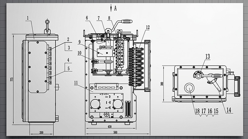
2. Decoding the Core Components: Mechanical Overview
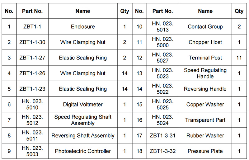
To understand the quality of the machine, we must look at its robust construction. Based on our detailed mechanical schematic, the locomotive is designed for easy maintenance and harsh environments:
Sealed Enclosure Design (Items 2-5): The system utilizes specially designed crimping nuts and elastic sealing rings. These create a dust-proof and moisture-proof environment, protecting sensitive internal electronics from coal dust and water spray.
User-Friendly Controls (Items 7, 8, 13, 14): Operators interact with the machine through the speed adjustment shaft assembly (Item 7), reversing handle (Item 14), and a dial-grip speed control handle (Item 13). The layout is ergonomic, allowing for precise control even while wearing heavy mining gloves.
Reliable Power Routing: The equipment features a dedicated chopper main body (Item 11), robust contactors (Item 10), and 11 terminal blocks (Item 12) that ensure secure and organized electrical connections.
Real-Time Monitoring: A digital voltmeter (Item 6) is housed directly in the top cover, allowing operators to constantly monitor battery status without opening the heavy, explosion-proof enclosure.
3. Inside the Electrical Schematic (Wiring Diagram)
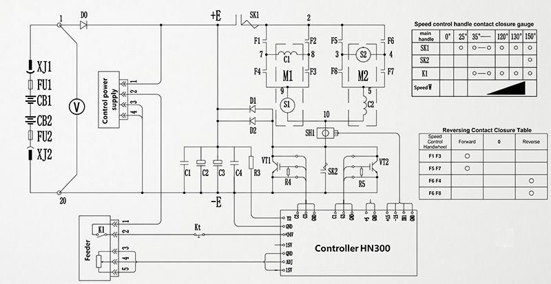
The electrical diagram provides the "brain" of the system, showing how components communicate to deliver power precisely where it is needed.
The Brain: HN300 Controller (The Main Chopper Unit): At the heart of the system is the HN300 controller. It receives analog signals from the speed setting unit (the throttle). It constantly monitors the system's voltage and current and makes split-second calculations to control the output.
Power Switching: IGBT Modules (VT1 & VT2): The diagram highlights two primary power switches, VT1 and VT2. These are the IGBT modules that chop the battery's DC voltage. By altering the duty cycle (the amount of time the power is "on" versus "off"), the controller dictates exactly how much power goes to the motors.
Dual Motor Drive System (M1 & M2): Unlike smaller locomotives, our 5-ton model features a dual-motor setup. The complex contactor system (F1-F8) works in tandem with the reversing handle. By switching these contactors, the polarity of the motors is reversed, allowing the locomotive to instantly change from forward to reverse.
Comprehensive Safety Protections: The wiring diagram clearly shows a robust safety architecture. It includes battery circuit breakers (CB1, CB2), main fuses (FU1, FU2) for short-circuit protection, and gate diodes to protect the controller from reverse current. There is also a dedicated emergency cut-off mechanism, ensuring that in the event of a fault, power is immediately isolated for operator safety.
4. How the Speed & Reversing Mechanism Works
The relationship between the physical handle and the electrical switches is defined in the Speed Handle Contact Sequence Table.
Starting Sequence (0° - 25°): This is the critical starting phase. The controller activates the main contactor, providing a low-voltage "creep" speed to break static friction and get the heavy load moving gently. This significantly reduces the initial current spike, protecting the battery and motor.
Acceleration Phase (35° - 130°): As the operator advances the handle, the IGBT modules (VT1 and VT2) gradually increase the average voltage. This creates a perfectly smooth, "stepless" acceleration curve up to maximum speed.
Directional Change: The Reversing Contactor Sequence Table explains the logic behind the forward/reverse switch. By simply moving the reversing handle, the F1-F8 contactors rearrange their connections to M1 and M2, allowing for seamless direction changes.
Conclusion
Choosing the right 5-ton battery locomotive is an investment in operational efficiency. The IGBT chopper system with its HN300 controller represents a significant leap forward in mining technology, offering superior energy efficiency, enhanced safety protections, and lower maintenance requirements compared to legacy models.
If you are looking to upgrade your underground fleet or require detailed technical specifications for your tender, please contact us today. Our engineering team is ready to provide customized solutions and full technical documentation for your specific mining requirements.
Sabrina He | Mining Machinery Specialist
With over 14 years of experience in the mining equipment industry, Sabrina He specializes in machinery selection, technical troubleshooting, and plant optimization.